Choosing Xlpe Cable Insulation is a project decision, not just a material preference. The right specification depends on operating voltage, load, installation conditions, and expected service life. A cable buried in damp soil faces different thermal demands from one installed in a ventilated industrial tray. Small details matter.
The International Energy Agency’s 2023 report, Electricity Grids and Secure Energy Transitions, estimates that annual grid investment must rise to more than USD 600 billion by 2030. That expansion makes dependable cable selection increasingly important, though the report does not prescribe a particular insulation material. For medium-voltage systems, IEC 60502-2 provides requirements for extruded-insulation cables and accessories within its specified voltage range. Engineers should check the applicable standard and project specification rather than rely on a product label alone. XLPE is widely used for its electrical and thermal performance, but performance depends on the complete cable system, including conductor size, screens, joints, and terminations. A neat datasheet is not a field test. Soil temperature, grouping, moisture, and installation workmanship can change the result. Even a sound calculation deserves a second look. This guide explains how to compare these factors and choose insulation suited to real operating conditions—not simply the lowest quoted price.
For XLPE cable selection, define the system voltage before comparing insulation thicknesses. IEC 60502-2 covers cables rated from 6 kV to 30 kV, while IEC 60287 provides methods for calculating current-carrying capacity. These are design references, not substitutes for project-specific checks. A cable that suits a nominal voltage may still be unsuitable for switching surges or temporary overvoltage.
Then quantify the load: normal current, peak demand, starting current, and expected growth. IEC 60502-2 specifies a typical maximum conductor temperature of 90°C in continuous operation and 250°C during short circuit, subject to cable design and fault duration. That matters. A tray packed with circuits sheds heat differently from a cable buried in moist soil. IEC 60287 calculations account for factors such as conductor losses and the surrounding material’s thermal resistivity. Record those inputs rather than assuming “standard” conditions.
Check ambient temperature, installation depth, grouping, solar exposure, and emergency loading. Also confirm how often the load peaks and how long faults may last. One detail is easy to overlook: soil conditions can change along a route, so one thermal-resistivity value may not represent the whole trench. I would treat early load estimates cautiously; they often look more certain than the site data behind them. Use verified measurements and the applicable IEC guidance to document the assumptions.
XLPE is not one uniform insulation choice. Standard XLPE is widely used in fixed power cables and offers strong electrical and thermal performance. Tree-retardant XLPE (TR-XLPE) includes additives that help slow water-tree growth, a concern in damp, buried routes. It may suit soil with persistent moisture, but it cannot compensate for damaged joints or poorly sealed terminations. Small details matter. HVDC-grade XLPE uses carefully controlled formulations to manage electrical stress and space charge. It is designed for direct-current systems, not simply a premium version of ordinary AC insulation. Real sites are messier.
Voltage class narrows the choice. IEC 60502-2 covers cables rated from 6 to 30 kV; IEC 60840 covers above 30 to 150 kV; IEC 62067 covers above 150 to 500 kV. These published IEC scopes define relevant test frameworks, not guaranteed service life. Compare them with the project’s voltage, moisture exposure, load cycling, and installation conditions. A cable running through a wet duct may need different water-tree protection from one in a dry indoor tray. Check compatibility with accessories, too. The label alone is not enough.
XLPE selection starts with the hottest conductor, not the average room temperature. IEC 60502-2 specifies a 90°C continuous conductor limit and a 250°C short-circuit limit, generally for up to five seconds. These are design limits, not permission to ignore hot spots. Check load cycles, grouping, soil conditions, and enclosure ventilation. A crowded tray can run hotter than the drawing suggests.
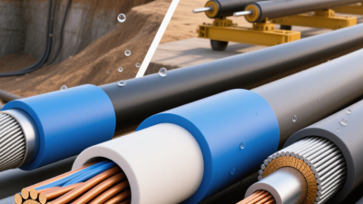
Moisture changes the risk. In wet ducts or buried routes, assess water entry at joints, terminations, and damaged sheaths, not just through the insulation. Chemical exposure needs equal care: list the actual fluids, concentrations, and contact temperatures, then verify compatibility using documented immersion data. “Oil resistant” is too vague. I would not assume one XLPE formulation suits every site; that shortcut deserves a second look.
Fire performance is a separate requirement. IEC 60332-1-2 uses a 1 kW flame in its single-cable flame-propagation test, but passing it does not establish circuit integrity during a fire. Specify the required fire test and smoke performance for the installation. Keep the test reports with the cable schedule. Small detail, big difference.
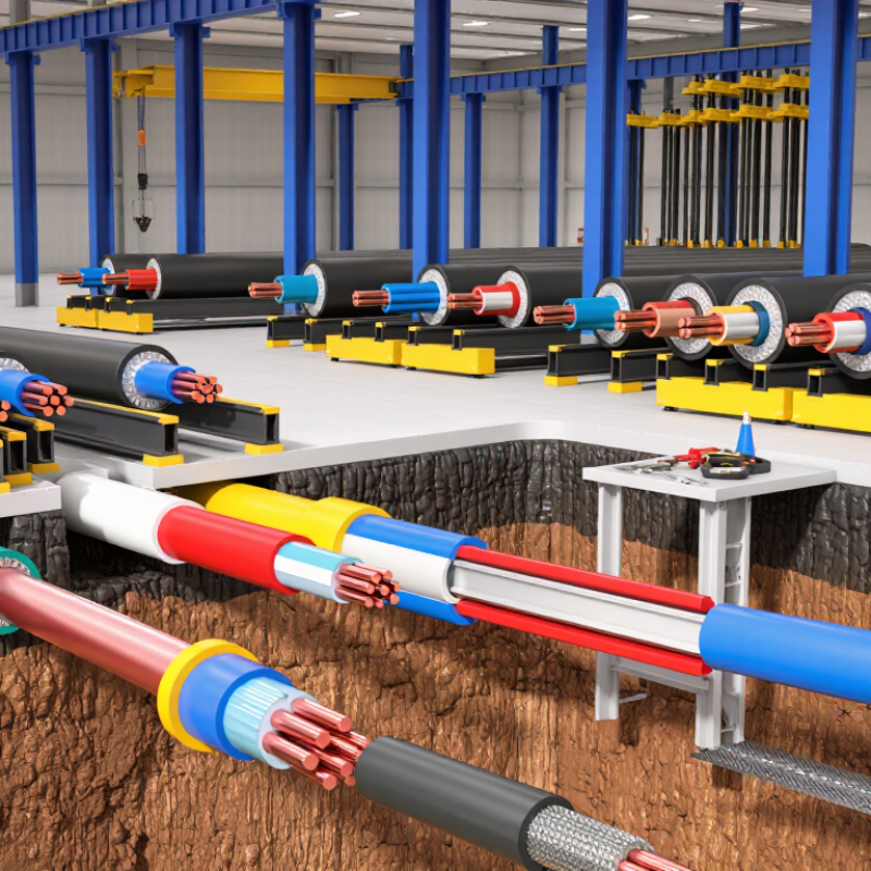
Choose the cable construction to suit the actual route, not just the project name. A cable pulled through a buried duct faces different stresses from one installed directly in soil. Direct-buried designs may need robust bedding protection and moisture-resistant layers. In a cable tray, support spacing, sunlight exposure, and mechanical damage become more relevant. Small details matter.
XLPE describes the insulation, not the complete cable design. Check conductor material and size, voltage rating, screen arrangement, outer sheath, and any armour or water-blocking features. A metallic screen may be required for particular voltage classes or earthing arrangements. Where cables pass through wet areas, confirm that the specified construction is suitable for persistent moisture, not merely occasional dampness. Do not assume one XLPE temperature rating applies to every installation; allowable current also depends on grouping, ambient temperature, and installation method.
Confirm the applicable electrical code and cable standard for the project location and voltage class. Compare the cable datasheet and test documentation with the installation drawings, including fire-performance requirements where relevant. A common design miss is selecting a cable by conductor size alone. Recheck the assumptions against the route; a specification that looks tidy on paper can still overlook a hot duct bank or a tight bend. Not always obvious.
| Project Condition | Typical Cable Construction | XLPE Insulation Considerations | Installation Guidance | Relevant Standards to Specify | Key Checks Before Selection |
|---|---|---|---|---|---|
| Indoor building distribution, dry locations, low voltage | Single-core or multicore copper/aluminum conductor; XLPE insulation; optional bedding and outer sheath; usually unarmored in protected routes | XLPE is commonly rated for a 90°C maximum continuous conductor temperature, subject to the cable standard and installation conditions. | Use in conduit, trunking, or cable tray where mechanical protection is adequate. Confirm the cable’s permitted installation method and ambient-temperature correction factors. | IEC 60502-1 for applicable power cables rated 0.6/1 kV or 1.8/3 kV; local wiring regulations for building installation. | Check conductor material and size, voltage rating, sheath properties, fire-performance requirements, and whether the route requires low-smoke or halogen-free materials. |
| Outdoor or underground distribution with risk of mechanical damage | Conductor; XLPE insulation; inner sheath or bedding; steel wire or steel tape armor for many multicore designs; outer sheath | Insulation thickness and electrical performance must match the rated voltage and applicable product standard. The outer sheath, rather than XLPE alone, provides much of the environmental protection. | Armoring can provide mechanical protection, but the design still needs suitable burial depth, bedding, warning tape, and protection against water or chemical exposure as required by the site. | IEC 60502-1 for applicable low-voltage power cables; IEC 60228 for conductor classes; local underground-cable and installation rules. | Confirm soil thermal resistivity, burial conditions, expected pulling forces, sheath resistance to soil and chemicals, and the required armor and bonding arrangement. |
| Single-core AC circuit requiring armor or additional mechanical protection | Single-core conductor with XLPE insulation and a non-magnetic armor arrangement, such as aluminum wire armor, where specified | XLPE insulation selection follows the circuit voltage and temperature requirements; armor material and bonding are important to avoid excessive induced losses and heating. | Coordinate cable spacing, cleating, armor bonding, and earthing with the system design. Do not assume a steel-armored single-core cable is suitable for AC service without engineering review. | IEC 60502-1 or IEC 60502-2, as applicable to voltage; relevant national installation rules and project specifications. | Verify phase arrangement, short-circuit duty, armor material, bonding method, magnetic effects, and the cable manufacturer’s installation limits. |
| Medium-voltage feeder, typically 6 kV to 30 kV rated voltage | Conductor; conductor screen; XLPE insulation; insulation screen; metallic screen; optional water-blocking layers, armor, and outer sheath | Semiconductive screens and controlled insulation interfaces are essential parts of the screened MV cable design. Select the rated voltage to suit the system earthing arrangement and maximum system voltage. | Use compatible terminations and joints designed for the cable’s insulation diameter and screen construction. Follow specified bending radii, pulling tension, and screen-earthing practices. | IEC 60502-2 covers power cables with extruded insulation for rated voltages from 6 kV (Um 7.2 kV) up to 30 kV (Um 36 kV). | Confirm U₀/U(Um), conductor size, metallic-screen fault-current capacity, water-blocking needs, installation environment, and accessory compatibility. |
| High ambient temperature or heavily loaded cable route | XLPE-insulated cable selected with conductor size and construction based on the actual thermal installation conditions | The commonly specified 90°C continuous conductor rating is not a guaranteed current-carrying capacity. Allowable current depends on the cable design, installation method, grouping, and ambient conditions. | Calculate ampacity for the actual route, including duct banks, trays, soil, grouping, ventilation, and solar exposure where relevant. Check temperature limits at joints and terminations. | Applicable IEC 60502 product standard, together with the project’s recognized ampacity calculation method and local electrical code. | Use project-specific thermal calculations; check overload and short-circuit conditions. Many IEC-based cable designs use a 250°C conductor short-circuit limit for a limited duration, subject to the applicable standard and cable data. |
| Public buildings, escape routes, or areas with stricter fire-performance requirements | XLPE-insulated cable with a sheath and construction selected for the required flame, smoke, and halogen performance; armor added only where needed | XLPE insulation alone does not establish a cable’s fire, smoke, or corrosivity classification. These properties depend on the complete cable construction and test results. | Specify performance for the installed cable type and route. Confirm whether the project requires flame propagation limits, reduced smoke, halogen-acid gas limits, or circuit integrity during fire. | IEC 60332-1-2 for a single cable vertical flame test; IEC 60754-1 for halogen acid gas content; IEC 61034-2 for smoke density measurement, where specified. | Check the exact test method and acceptance criteria in the project specification. Do not treat a result from one fire test as proof of compliance with another. |
| Wet, coastal, or water-exposed installation | XLPE-insulated cable with a suitable moisture-resistant outer sheath; longitudinal or radial water-blocking features where required by the design | XLPE is not, by itself, a complete water-ingress protection system. Cable screens, interfaces, sheath, and water-blocking components must be appropriate for the exposure. | Use cable designed for the expected exposure and install compatible sealed joints and terminations. Consider UV, salt, chemicals, and the possibility of water migration along the cable. | Applicable IEC 60502 voltage-class standard and project-specific water-penetration, sheath, and environmental test requirements. | Define whether exposure is temporary or continuous, the expected water pressure, chemical contact, UV exposure, and required sheath and water-blocking performance. |
| Selection note: Standards and ratings depend on the cable voltage class, construction, and jurisdiction. Confirm the current edition of each standard, local code requirements, project specifications, and cable test documentation before procurement. Values shown are typical design guidance, not a substitute for a project-specific cable calculation. | |||||

A technical review should begin with the cable’s actual duty, not a generic insulation label. Confirm system voltage, conductor size, expected load, fault duration, and ambient temperature. XLPE’s thermal rating matters, but the cable must also suit the installation route. A tray exposed to sunlight differs from a buried duct with wet soil. Check insulation thickness, dimensional tolerances, screen design, and sheath requirements against the project specification. Small gaps in the review can become costly later. I would not rely on a catalogue value alone.
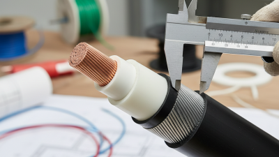
Testing should connect the stated performance to measurable evidence. Review routine and sample test reports, including conductor resistance, insulation dimensions, and voltage withstand results. For medium- or high-voltage applications, examine partial-discharge or other specified electrical test data where relevant. Confirm that test methods, limits, and acceptance criteria match the applicable standards and project requirements. At site, inspect drum condition, verify cable markings, and use an approved commissioning test procedure. Record the instruments, calibration status, and results. One detail is easy to miss: a field test is not automatically equivalent to a factory test. If an unfamiliar result appears, pause and ask the cable engineer to interpret it before installation continues.