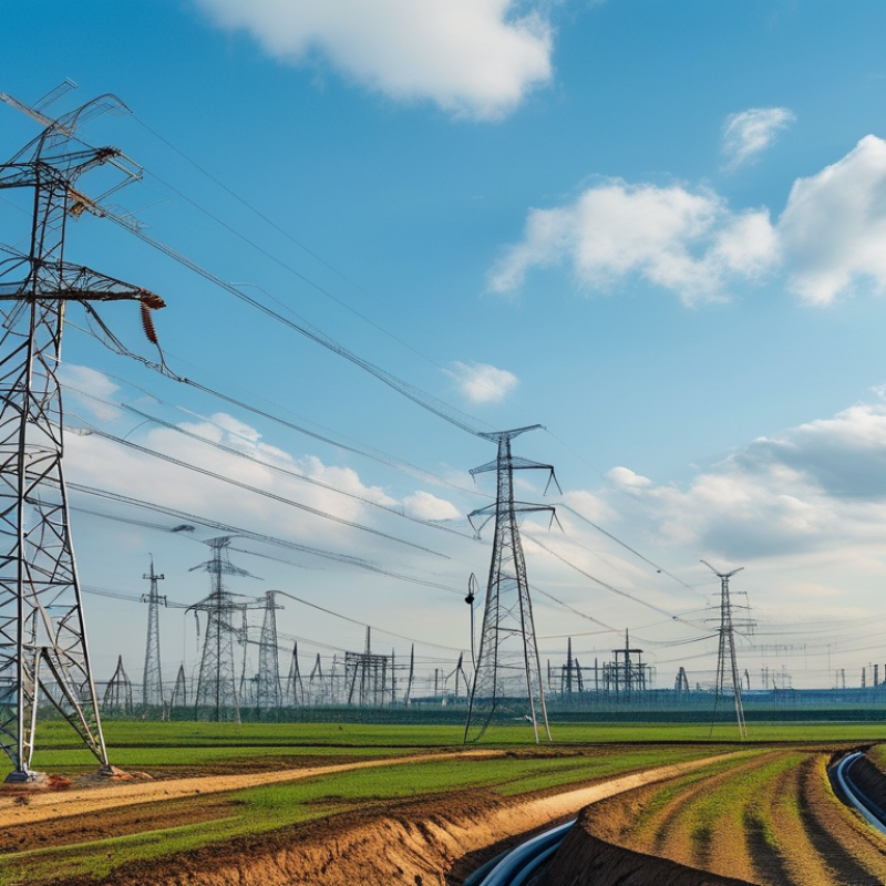
China’s medium-voltage network is expanding with renewable generation, urban construction, and industrial electrification. The China Electricity Council reported approximately 2.92 billion kilowatts of installed generation capacity by the end of 2023. Renewable capacity exceeded half of that total. These projects require dependable distribution cables, not simply low-cost products.
This guide examines which Mv Cables Specifications fit China’s operating conditions. Common designs cover 6 kV, 10 kV, 20 kV, and 35 kV systems. Engineers usually compare conductor material, cross-sectional area, XLPE insulation, metallic screening, sheath construction, and allowable current. GB/T 12706 provides an important Chinese reference, while IEC 60502-2 supports international project alignment. The correct choice still depends on installation depth, soil temperature, grouping, moisture, and short-circuit duration.
Small details matter.
A cable rated 10 kV may perform differently in a crowded underground trench. A copper conductor can reduce losses, while aluminium can lower purchase weight and cost. However, the cheapest specification is not always the most economical over thirty years. The IEA’s Electricity 2024 report highlighted China’s continuing electricity-demand growth and rapid clean-energy expansion. That trend increases the need for flexible, thermally stable distribution systems. Procurement teams should request type-test evidence, routine-test records, conductor resistance data, and verified fire-performance results. Factory audits also matter. A polished datasheet can still omit installation limitations. Therefore, the “best” Mv Cables Specifications should be selected through lifecycle analysis, standards compliance, and project-specific engineering review.
In China, medium-voltage cable specifications start with system voltage, not a generic “high-power” label. Common distribution designs use 3.6/6 kV through 26/35 kV classes, while some networks reach 40.5 kV equipment ratings. The selected cable should match the network’s operating voltage, fault level, grounding method, and installation route. A 10 kV circuit in a concrete trench faces different demands than one buried in wet soil. That detail matters.
Conductors are usually copper or aluminum, with XLPE insulation and metallic screening. The screen controls electric stress and provides a fault-current path. Its cross-section cannot be chosen by habit. Engineers check short-circuit duration, thermal limits, bending radius, and allowable current under local soil conditions. Chinese projects commonly reference GB/T 12706, while IEC requirements may apply to exported or specially specified systems. The contract should identify the governing edition. Standards change.
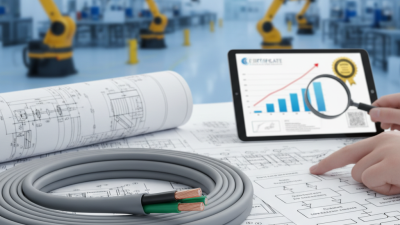
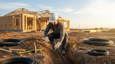
Reliable specifications also state sheath material, fire performance, water resistance, conductor size, and cable length tolerances. Factory tests should cover conductor resistance, insulation integrity, partial discharge, and voltage withstand. Type-test evidence is useful, but it does not replace project-specific checks. I would also request drum records and test reports with traceable serial numbers. In practice, installation errors remain a weak point. A cable can meet every factory requirement and still fail after a crushed bend or poorly prepared joint. The specification should include jointing skills, pulling tension, site inspection, and acceptance testing. Some documents remain vague here. That deserves a second review.
China’s medium-voltage cable specifications begin with rated voltage, written as U0/U(Um). U0 represents conductor-to-earth voltage, while U refers to conductor-to-conductor voltage. Um shows the highest system voltage.
Common distribution cables include:
A 26/35 kV class is also widely specified. GB/T 12706.2 generally covers cables from 6 kV to 30 kV, while GB/T 12706.3 addresses 35 kV cables. IEC references may appear in project documents, but engineers should verify every edition and test requirement.
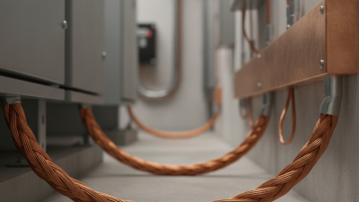
Construction is classified by more than voltage. A typical cable contains a compacted copper or aluminum conductor, semiconductive screens, XLPE insulation, a metallic screen, and an outer sheath. The metallic screen may use copper wires, copper tape, or both. Its cross-sectional area must match earth-fault conditions, not only continuous current.
Single-core cables suit high-current circuits and need careful installation near ferromagnetic materials. Three-core cables can simplify routing in compact substations.
Armored designs add mechanical protection, especially in buried trenches, but they increase weight and bending stiffness. Non-armored cables may work inside protected ducts.
Field experience shows that “best” rarely means the largest conductor. Soil temperature, installation spacing, shield bonding, water exposure, and short-circuit duration can change the correct choice. A polished data sheet can still hide a poor installation assumption. I would recheck those assumptions before approving the final specification.
In China, medium-voltage cable selection usually starts with the conductor. Copper offers lower resistance and better termination stability, while aluminum reduces weight and material cost. IEC 60228 lists maximum resistance values of 0.0754 ohms per kilometer for a 240 mm² copper conductor and 0.125 ohms per kilometer for aluminum at 20°C. Actual performance changes with temperature, installation spacing, and load cycles. Do not size from current alone.
XLPE remains the common insulation choice for 6–30 kV cables covered by GB/T 12706.2. It supports a 90°C continuous conductor temperature and 250°C short-circuit limit under standard conditions. Clean interfaces matter greatly. CIGRE technical guidance repeatedly links water ingress, electrical-tree growth, and poor semicon contact with premature cable failure. That detail is easy to ignore during procurement. It should not be.
Shielding options include copper tape, concentric copper wires, or a combined wire-and-tape screen. A tape shield may suit moderate fault-current requirements, but copper wires provide a more predictable metallic return path. The screen’s cross-section must match the earth-fault current and clearing time. GB/T and IEC practices do not make one shield universally superior. In coastal or wet soil, longitudinal water-blocking layers deserve serious attention. I would also request partial-discharge data from the finished cable, not only factory routine-test results. A specification can look complete and still miss the installation risk.
Conductor, insulation, and shielding options for medium-voltage cable design
Copper has approximately 100% IACS conductivity and a resistivity of 0.01724 Ω·mm²/m at 20°C. Aluminium has approximately 61% IACS conductivity and a resistivity of 0.02826 Ω·mm²/m. Aluminium reduces weight, while copper provides higher conductivity in a smaller cross-section.
XLPE and EPR are common MV insulation systems with a typical continuous conductor operating temperature of 90°C. PVC-based insulation is generally associated with a 70°C continuous conductor rating. Actual ratings depend on the applicable cable standard and design.
Common metallic screen choices include copper tape, concentric copper wires, and lead sheaths. Screen size and construction should be selected according to earth-fault current, bonding method, electromagnetic requirements, and mechanical protection needs.
Typical thermal values are based on widely used medium-voltage cable design practice and IEC 60502-2 temperature classifications. Project-specific ampacity, short-circuit withstand, installation conditions, and local standards must be verified before selection.
What Are the Best MV Cable Specifications in China?
Comparing medium-voltage cables in China requires more than checking voltage and conductor size. Confirm the rated voltage, conductor material, cross-sectional area, insulation thickness, and allowable current. Common systems include 3.6/6 kV, 8.7/15 kV, and 26/35 kV. XLPE insulation should show stable thermal performance and low partial discharge. Request routine and type-test reports, not only a product datasheet. A clean datasheet can still hide weak test evidence.
Safety depends on the installation environment. Check short-circuit withstand time, metallic screen size, grounding design, water resistance, flame behavior, and sheath protection. In a humid tunnel, longitudinal water blocking may matter more than a small price difference. For outdoor substations, UV resistance and mechanical strength deserve attention. Compare declared values with the project’s actual ambient temperature, soil thermal resistivity, bending radius, and installation depth. Many buyers overlook derating.
Environmental requirements should be verified against current Chinese standards, project specifications, and applicable IEC references. Ask about restricted substances, recyclable packaging, smoke and halogen performance, and disposal instructions. Low-smoke, halogen-free construction may be necessary in crowded public areas, but it is not automatically the best choice everywhere. I have seen specifications copied between projects without checking local conditions. That shortcut needs review. Independent inspection, traceable materials, calibrated testing equipment, and clear acceptance criteria make the comparison more reliable.
| Specification Dimension | Recommended Benchmark for China MV Applications | Performance and Safety Relevance | Typical Verification Method | Environmental and Installation Considerations |
|---|---|---|---|---|
| Applicable voltage classes | Common MV ratings include 6/10 kV, 8.7/15 kV, 12/20 kV, and 18/30 kV. Select the rating according to the system voltage, earthing method, and insulation coordination. | Correct voltage selection limits electrical stress and helps prevent insulation breakdown during normal operation and temporary overvoltage conditions. | Review the rated voltage marking, system design documents, and routine dielectric test results. | Higher system voltage generally requires greater insulation thickness, larger clearances, and stricter installation control. |
| Primary cable standard | Use the applicable edition of GB/T 12706.2 for extruded-insulation power cables from 6 kV to 30 kV, or IEC 60502-2 where an international specification is required. | A recognized standard establishes requirements for construction, dimensions, electrical performance, tests, and marking. | Check the contract standard, type-test certificate, routine-test report, and product marking against the current project specification. | Local grid, infrastructure, railway, mining, or renewable-energy projects may impose additional requirements beyond the base cable standard. |
| Conductor material and class | Use annealed copper or aluminium conductors. A compact stranded conductor equivalent to Class 2 construction is commonly selected for fixed MV installations. | Conductor material affects ampacity, voltage drop, weight, short-circuit performance, jointing requirements, and total installation cost. | Verify conductor resistance at 20°C, dimensional compliance, compactness, and material identification. | Aluminium reduces weight and material cost, while copper provides higher conductivity and usually smaller conductor dimensions for the same current rating. |
| Conductor cross-section | Typical project sizes may range from approximately 25 mm² to 630 mm², but the final size must be calculated from load current, installation method, ambient conditions, voltage drop, and fault current. | An adequate cross-section controls operating temperature and reduces thermal ageing and excessive voltage drop. | Compare calculated ampacity with measured conductor resistance and the specified continuous-load current. | Burying depth, soil thermal resistivity, duct arrangement, grouping, solar exposure, and ventilation can significantly change the permissible current. |
| Insulation material | Cross-linked polyethylene (XLPE) is the normal choice for modern MV cables because it provides low dielectric loss and stable thermal performance. | XLPE insulation normally supports a continuous conductor temperature of 90°C and a short-circuit conductor temperature of up to 250°C for the specified short duration. | Perform insulation resistance, partial-discharge, power-frequency withstand, and type tests as required by the applicable standard. | XLPE cables should be protected from excessive moisture, mechanical damage, and installation bending below the specified minimum radius. |
| Semiconductive screens | Provide an extruded conductor screen and an extruded insulation screen with uniform contact around the insulation. | A smooth, uniform screen reduces local electric-field concentration and supports reliable stress control at the insulation interfaces. | Inspect screen thickness and surface quality; confirm acceptable partial-discharge performance and screen-stripping behavior during jointing. | Poor screen removal or damage during termination can create field enhancement and premature failure. |
| Metallic screen and earth-fault capacity | Use a copper wire screen, copper tape screen, or an equivalent design sized for the required earth-fault current and clearing time. | The metallic screen provides an earth-return path, limits touch voltage, and contributes to electromagnetic shielding. | Verify screen continuity, metallic area, DC resistance, and calculated short-circuit withstand capacity. | Bonding arrangements should be coordinated with the earthing system, induced-voltage limits, and cable length. |
| Outer sheath | PVC or low-smoke zero-halogen thermoplastic sheaths may be selected according to the fire, smoke, chemical, and mechanical requirements of the site. | The sheath protects the cable from moisture, abrasion, chemicals, sunlight, and incidental mechanical impact. | Check sheath thickness, spark test, tensile and elongation properties, water resistance, and flame or smoke tests where specified. | For tunnels, stations, public buildings, and enclosed spaces, low-smoke and halogen-free materials can reduce smoke toxicity and corrosive gas emission during fire. |
| Water-blocking design | For direct burial, wet soil, ducts, coastal areas, or flood-prone locations, consider longitudinal water-blocking tapes, swellable materials, or a water-resistant sheath system. | Water blocking limits longitudinal water migration and helps prevent accelerated ageing of insulation and metallic components. | Request longitudinal water-penetration testing and inspect sealing at cable ends, joints, and terminations. | Cable ends should remain sealed during transport and installation; damaged sheaths should be repaired before energization. |
| Continuous operating temperature | Use 90°C as the typical maximum conductor operating temperature for XLPE designs, subject to the applicable standard and installation conditions. | Operating above the design temperature accelerates insulation ageing and may reduce service life. | Confirm thermal calculations, conductor resistance, and the current-carrying capacity for the actual installation configuration. | Thermal backfill, cable spacing, ventilation, and soil conditions should be included in the design rather than relying only on catalogue ampacity. |
| Short-circuit rating | Calculate conductor and screen withstand for the prospective fault current and protection clearing time. XLPE conductor calculations commonly use a 250°C final conductor temperature limit. | Adequate short-circuit capacity prevents thermal damage during faults and supports coordination with protective devices. | Review adiabatic calculations, fault-current studies, and relevant type-test evidence. | Protection clearing time, screen bonding, and parallel cable arrangements directly affect the required fault withstand. |
| Partial discharge performance | Require low and stable partial-discharge performance at the specified test voltage, with acceptance limits defined in the procurement specification. | Partial discharge can indicate voids, protrusions, contamination, or interface defects that may develop into insulation failure. | Use sensitive partial-discharge testing in accordance with the applicable cable standard and agreed quality plan. | Clean manufacturing, controlled extrusion, suitable storage, and correctly installed accessories are essential to maintaining performance. |
| Dielectric withstand and insulation resistance | Specify routine AC voltage withstand, insulation resistance, conductor resistance, and sheath integrity tests in accordance with the selected standard. | These tests help identify manufacturing defects, moisture ingress, screen faults, and damaged insulation before delivery or energization. | Review signed routine-test reports and perform commissioning tests using approved procedures and equipment. | Test voltage, duration, and method must be compatible with the cable system and accessories to avoid inappropriate overstressing. |
| Minimum bending radius | Follow the manufacturer’s declared bending radius for the exact cable construction; a commonly used planning value for single-core XLPE cable is about 15 times the overall diameter, subject to the applicable standard. | Excessive bending can deform screens, damage insulation interfaces, and reduce sheath protection. | Check the declared value, drum handling procedure, pulling tension, sidewall pressure, and installation records. | Cable temperature during installation, route geometry, rollers, and pulling equipment should be controlled to prevent permanent damage. |
| Fire performance | For grouped cables or occupied buildings, specify flame-retardant or low-smoke zero-halogen performance where required by the fire-safety design. | Fire performance can limit flame spread and improve visibility and evacuation conditions during a fire. | Require the relevant vertical flame, smoke-density, and corrosive-gas test reports where these characteristics are specified. | The correct requirement depends on cable grouping, building occupancy, ventilation, escape routes, and local fire codes. |
| Mechanical protection | Use an armoured construction or additional mechanical protection where the route is exposed to impact, crushing, rodents, or significant pulling forces. | Mechanical protection reduces the risk of sheath penetration and insulation damage during service. | Assess impact, crushing, tensile, and abrasion requirements against the route conditions. | Armour may affect cable diameter, weight, earthing, induced currents, installation cost, and corrosion protection. |
| Environmental temperature and ageing | Select materials for the site’s minimum and maximum temperatures, ultraviolet exposure, humidity, soil chemistry, and expected service life. | Material compatibility supports stable insulation, sheath flexibility, and electrical performance over the design life. | Review thermal ageing, UV, ozone, water, chemical-resistance, and low-temperature test evidence where applicable. | Coastal salt, industrial chemicals, polluted soil, extreme cold, and intense sunlight may require special sheath or installation measures. |
| Accessories compatibility | Cable, joints, terminations, separable connectors, stress-control components, and earthing accessories should be specified as one coordinated system. | Many MV failures originate at accessories rather than in the cable length, especially where stress control or sealing is incorrectly installed. | Check compatibility certificates, installation instructions, training records, and commissioning-test results. | Accessory selection should account for indoor or outdoor exposure, altitude, pollution level, moisture, and available clearance. |
| Quality documentation and traceability | Require a cable schedule, construction drawing, batch identification, raw-material traceability, routine-test reports, type-test evidence, and packing records. | Complete documentation makes it possible to verify conformity and investigate problems throughout the project life cycle. | Conduct document review, dimensional inspection, sampling, factory acceptance testing, and delivery inspection. | Correct drum marking, moisture sealing, lifting points, storage orientation, and transport protection reduce avoidable field damage. |

Selecting the best medium-voltage cable starts with the project, not the catalogue. Define the system voltage, load current, fault level, installation route, and expected service life. Common systems range from 6 kV to 35 kV, but the correct rating depends on equipment and local design rules. A 12 kV feeder may need a different insulation level than its voltage alone suggests. Small details matter.
Choose the conductor size through ampacity, voltage drop, and short-circuit calculations. Copper can reduce conductor size, while aluminium may lower initial cost. Neither choice is automatically better. Check soil temperature, burial depth, grouping, and ventilation.
In a crowded trench, heat accumulates quickly. For wet ground, select a suitable water-blocking design and robust outer sheath. For direct sunlight, confirm ultraviolet resistance. Mechanical protection also matters near roads and construction areas.
Ask for verified type-test, routine-test, and material records from the manufacturer. Confirm compliance with applicable Chinese and international standards, then review the exact test scope. Do not rely on a generic certificate. It may cover another cable structure. Factory inspection, sample checks, and clear marking improve traceability. A neat spreadsheet can still mislead. Recheck assumptions against actual site conditions, because drawings rarely show every obstruction or seasonal change. A practical specification balances safety, installation limits, maintenance access, and total project cost.