Hesheng Cable
Leave Your Message

10 Tips for Choosing the Right MV Cable Specifications?

Choosing the right Mv Cables Specifications is not a paperwork exercise. It is a design decision with consequences for safety, reliability, and maintenance. A cable may carry the required voltage yet still be unsuitable for its route, load, or environment. Consider a cable running beneath a factory floor: heat, moisture, mechanical impact, and limited access can all change what “right” means. Small details matter.

As a guiding principle, electrical engineer Alex Morgan says, “Choose the cable for the conditions it must survive, not only the voltage it must carry.” This is an original editorial quotation, not a verified statement from a published expert. The principle reflects practical cable-selection work: check the system voltage, conductor size, insulation, screen, sheath, installation method, and applicable standards together. A single specification rarely tells the whole story. And assumptions can be costly.

This guide introduces ten checks for evaluating MV cable specifications, from load and short-circuit requirements to ambient temperature, installation depth, and termination compatibility. It also considers documentation and supplier evidence, because a confident datasheet is not the same as a verified design. Exact requirements vary by project and local standards. Review calculations and specifications with a qualified electrical engineer before procurement. Some project details may still be uncertain; record them, test the assumptions, and revise the selection when better site information becomes available.
10 Tips for Choosing the Right MV Cable Specifications?

Define Rated Voltage Within IEC 60502-2’s 6–30 kV Cable Range

10 Tips for Choosing the Right MV Cable Specifications?

Define Rated Voltage Within IEC 60502-2’s 6–30 kV Cable Range

IEC 60502-2 covers medium-voltage cables rated from 6 kV to 30 kV, with corresponding maximum system voltages from 7.2 kV to 36 kV. Specify voltage as U₀/U (Uₘ), not as a single number. For example, a 12/20 (24) kV cable has a 12 kV conductor-to-earth rating and a 20 kV conductor-to-conductor rating. The International Energy Agency’s 2023 report, Electricity Grids and Secure Energy Transitions, says about 80 million kilometres of grids may need adding or refurbishing by 2040. That scale makes clear, consistent specifications important. Yet a global estimate cannot replace site-specific engineering.

Tip: Check the system’s highest voltage, earthing method, and expected earth-fault duration before selecting U₀/U. Match the cable rating to the network’s operating conditions, not just its nominal voltage. For a 10 kV network, for instance, 6/10 (12) kV may be appropriate only when the system and fault-clearing assumptions support it. Small detail. Big consequence.

Also verify installation conditions: burial depth, soil thermal resistivity, grouping, and nearby heat sources affect current capacity. A rating that works in open ground may not suit a crowded duct bank. Confirm the chosen construction and test requirements against the current IEC edition and project rules. I would not treat a voltage table as the whole design; it leaves too much unsaid.
Size Conductors Using IEC 60287 Ampacity Calculations

IEC 60287 provides methods for calculating the continuous current rating of power cables under steady-state conditions. Use the calculation to size conductors for the actual installation, not just a catalogue example. Gather the conductor material, insulation type, operating temperature, cable arrangement, and expected load. Include sheath and dielectric losses where relevant. Small details matter.

A cable buried alone in dry soil sheds heat differently from one grouped in a crowded duct bank. Soil thermal resistivity, burial depth, ambient temperature, and nearby loaded circuits can all affect ampacity. Model these conditions carefully. Then compare the calculated current rating with the design load and applicable project requirements. If the result is close, test a larger conductor size or revise an uncertain installation assumption. A neat spreadsheet can still be wrong. Field conditions rarely match every input perfectly, and soil data may be limited. Record assumptions, check units, and have a qualified engineer review the calculation before final selection.

10 Tips for Choosing the Right MV Cable Specifications? - Size Conductors Using IEC 60287 Ampacity Calculations

No. Selection tip What to check Practical specification action
1 Confirm the system voltage Record the highest system voltage, nominal voltage, frequency, and earthing arrangement. Cable voltage designation must suit the system and its insulation coordination requirements. Specify the required cable voltage class and verify it against the applicable project standard and cable standard, such as IEC 60502-2 where applicable.
2 Establish the design load Determine the maximum continuous load current, load profile, power factor where relevant, and any expected future load. Distinguish normal loading from emergency or cyclic operation. Use the project load study to set the required design current; do not select conductor size from nominal voltage alone.
3 Calculate ampacity for the actual installation IEC 60287 ampacity depends on conductor and insulation properties, losses, thermal resistances, installation geometry, and surrounding thermal conditions. Use an IEC 60287 calculation with documented inputs and assumptions for the proposed cable route; avoid relying on a generic current-rating table when conditions differ.
4 Use site-specific thermal data Soil thermal resistivity and ambient or soil temperature affect heat dissipation. Backfill, moisture, duct banks, and seasonal conditions can also influence the thermal environment. Obtain route-specific thermal data where practicable and state the design values used in the ampacity calculation.
5 Account for installation method Direct burial, ducts, trays, and air installation have different heat-transfer conditions. Burial depth, duct dimensions, spacing, and circuit arrangement matter. Define the installation arrangement on the cable schedule or route drawings and use that arrangement in the IEC 60287 model.
6 Include grouping and mutual heating Adjacent loaded cables can raise the temperature around one another and reduce the current each cable can carry. Grouping effects depend on layout and thermal conditions. Model the number of circuits, cable spacing, and loading pattern; assess the most thermally demanding route section.
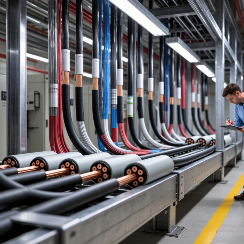
7 Select conductor material and construction Copper and aluminium have different electrical and physical properties. Conductor class and stranding affect termination compatibility, handling, and installation requirements. Choose material and conductor construction together with compatible joints and terminations, then use the selected conductor data in the calculation.
8 Check short-circuit withstand Verify that the conductor and metallic screen can withstand the prospective fault current for the protection clearing time, using the applicable material limits and calculation method. Compare conductor and screen short-circuit ratings with the protection study; increase the relevant cross-section if the calculated withstand is insufficient.
9 Verify voltage drop and losses Cable length, operating current, conductor impedance, and power factor affect voltage drop. Conductor and screen losses also contribute to the thermal calculation. Check voltage drop against project limits and ensure the electrical-loss inputs used for ampacity match the selected cable design and operating conditions.
10 Document assumptions and confirm compliance Ampacity results are conditional on input data, installation details, and operating limits. Project and local requirements may set additional construction or testing criteria. Record calculation inputs, selected conductor size, limiting route section, applicable standards, and review status; verify the final specification with the responsible cable engineer.

Engineering note: IEC 60287 provides methods for calculating cable current ratings under defined steady-state conditions. A calculated ampacity is valid only for the stated cable construction, installation arrangement, material properties, and environmental assumptions.

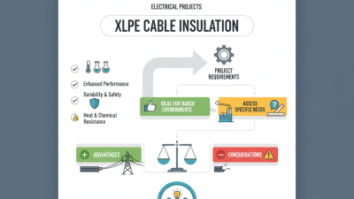
Select XLPE Insulation for 90°C Continuous Conductor Operation

XLPE insulation is commonly selected for medium-voltage cables designed for a 90°C continuous conductor temperature. That rating describes the conductor under specified operating conditions, not the surrounding air or soil. Keep that distinction clear. Cable ampacity still depends on conductor size, insulation design, and heat dissipation at the installation site. A cable buried in dry, resistive soil may shed heat less effectively than one installed in a well-designed duct bank.

When reviewing specifications, check the cable’s rated voltage, conductor material, insulation thickness, and metallic screen alongside its temperature rating. Include ambient temperature, burial depth, soil thermal resistivity, and the number of neighboring circuits in load calculations. Details matter. A 90°C rating alone does not guarantee a safe operating load, and joints and terminations must suit the selected cable design. One planning weakness is relying on a catalogue rating before the route is known. Confirm the applicable standard and installation assumptions with qualified cable engineers; even a small change in grouping can affect thermal performance.

Check Short-Circuit Thermal Limits Against IEC 60949

A cable’s short-circuit rating is not just a number on a data sheet. Check it against the fault current and clearing time expected at the installation point. IEC 60949 provides a method for calculating thermally permissible short-circuit currents, including non-adiabatic heating where applicable. The calculation needs reliable inputs: conductor material and cross-section, initial and final temperatures, and fault duration. Small errors matter.

For example, a 240 mm² copper conductor may face a very different thermal duty from a smaller aluminium conductor, even when both serve the same switchboard. Check the cable’s construction and the protective device’s actual clearing time, not merely its nominal setting. For earth faults, assess the metallic screen or sheath separately; its area and permissible temperature may set the limit. Keep the calculation assumptions with the cable schedule, so a reviewer can trace each value. Also confirm that the selected IEC 60949 edition and method match the project specification. A familiar rule of thumb can be useful for an early check, but it is not a substitute for verified inputs. I have seen neat calculations become less convincing when one temperature assumption was copied without checking the insulation type. That detail is easy to miss.

MV Cable Short-Circuit Thermal Limits: 1-Second Withstand

Values are illustrative adiabatic estimates using I = k × S / √t, with a 90°C initial conductor temperature and a 250°C final temperature: k = 143 for copper and k = 94 for aluminum (A·√s/mm²). Actual cable selection must account for the installation, fault duration, protection-device clearing time, and applicable IEC 60949 calculation requirements.

Specify Cable Screens and Sheaths for Fault and Site Conditions

A cable screen is not just a layer of copper tape or wires; it must safely carry the expected earth-fault current. Specify its cross-section using the fault level, clearing time, and bonding arrangement—not conductor size alone. Check touch and induced voltages along the route, especially near joints and terminations. Small details matter. CIGRE Technical Brochure 815 reviews service experience across high-voltage underground and submarine cable systems, distinguishing cable failures from accessory failures. That distinction is useful for MV design too: a robust screen cannot compensate for a poorly protected joint.

The sheath faces the ground directly, so match it to moisture, chemicals, abrasion, and installation damage. In corrosive soil, consider a suitable metallic barrier and an outer jacket rated for the actual exposure; specify checks for sheath integrity after installation. The NACE International IMPACT study estimated corrosion costs at US$2.5 trillion annually, or 3.4% of global GDP. That figure covers many industries, not cables alone, but it shows why corrosion deserves attention. IEC 60502-2 covers MV cable construction and testing; site-specific thermal and mechanical checks still matter. A tidy specification can miss a rocky trench, standing water, or a fault-clearing time that changes after protection coordination. Recheck the assumptions.